GPIO IN, OUT (Arduino IDE + ESP32 ボードマネージャ)
プログラムの書き方
LED やスイッチを使う上でよく使われる関数を紹介する.
pinMode( ピン番号, OUTPUT);    //ピンを出力に設定
digitalWrite(ピン番号, HIGH);  //電圧を HIGH (3.3V, 定格) に. LED が光る.
digitalWrite(ピン番号, LOW);   //電圧を LOW (0V) に. LED が消える.

pinMode( ピン番号, INPUT);        //ピンを入力に設定
pinMode( ピン番号, INPUT_PULLUP); //ピンを入力に設定. 内部でプルアップする.
State = digitalRead( ピン番号 );  //入力値の取得. status の値は HIGH (1), LOW (0)のどちらかをとる.
詳細は Language Reference の "Digital I/O" の項目, リファレンス デジタル入出力関数の項目, を参照されたい.
L チカ
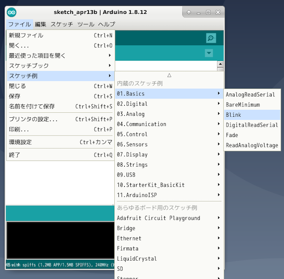
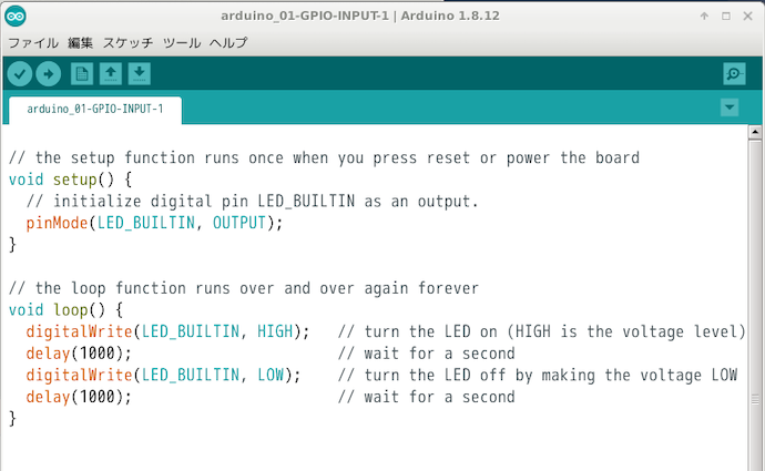
電子工作における Hello World と言える L チカを実行するためのプログラムを作成する. 基本的なプログラムは「スケッチ例」に含まれているので, それを利用するのが良い.

スケッチ例に LED の接続先 GPIO (変数名: LED_BUILTIN) を加えたものが以下のプログラムである. このプログラムは GPIO 13 に接続されている LED を 1 秒間隔で点灯させるものである.
1  const int LED_BUILTIN = 13;
2
3  // the setup function runs once when you press reset or power the board
4  void setup() {
5    // initialize digital pin LED_BUILTIN as an output.
6    pinMode(LED_BUILTIN, OUTPUT);
7  }
8
9  // the loop function runs over and over again forever
10 void loop() {
11   digitalWrite(LED_BUILTIN, HIGH);   // turn the LED on (HIGH is the voltage level)
12   delay(1000);                       // wait for a second
13   digitalWrite(LED_BUILTIN, LOW);    // turn the LED off by making the voltage LOW
14   delay(1000);                       // wait for a second
15 }
- 1 行目: LED の接続される GPIO を指定
- 6 行目: 初期化関数 (setup()) 内で LED の接続されているピンを出力に設定.
- setup() 関数は, マイコンボードの電源を入れた時やリセットした時に 1 回だけ実行される関数であり, 変数やピンの入出力モードの初期化, ライブラリの準備などに使用される.
- 11, 13 行目: LED の点灯・消灯.
- 無限ループで繰り返し行われる処理は loop() 関数内に書く.
- 12,14 行目: 1 秒だけ動作を止める. delay() は, プログラムを指定した時間だけ止める関数 (引数の単位はミリ秒).

L チカ + スイッチ (1)
スイッチと LED を使う例がやはりスケッチ例に存在するので, それを利用する.

スケッチ例の LED の接続先 GPIO (変数名 ledPin) は 13 から変更しなくて良い. スイッチの接続先 GPIO (変数名 buttonPin) をスイッチ 4 (GPIO19) に変更してみる.
1  // constants won't change. They're used here to set pin numbers:
2  const int buttonPin = 19;     // the number of the pushbutton pin
3  const int ledPin =  13;      // the number of the LED pin
4
5  // variables will change:
6  int buttonState = 0;         // variable for reading the pushbutton status
7
8  void setup() {
9    // initialize the LED pin as an output:
10   pinMode(ledPin, OUTPUT);
11   // initialize the pushbutton pin as an input:
12   pinMode(buttonPin, INPUT);
13 }
14
15 void loop() {
16   // read the state of the pushbutton value:
17   buttonState = digitalRead(buttonPin);
18
19   // check if the pushbutton is pressed. If it is, the buttonState is HIGH:
20   if (buttonState == HIGH) {
21     // turn LED on:
22     digitalWrite(ledPin, HIGH);
23   } else {
24     // turn LED off:
25     digitalWrite(ledPin, LOW);
26   }
27 }
- 2 行目: スイッチの接続される GPIO を指定.
- 12 行目: スイッチの接続されているピンを入力に設定
- 17 行目: スイッチの入力値を取得
- 20-22 行目: スイッチが入っていたら LED を ON に.
- 23~25 行目: スイッチが入ってなければ LED を OFF に.
実は上記をそのまま実行するとうまく動かない. スイッチ 4 をオンにしても LED1 の点灯が何やら不安定なことが確認できるだろう. 上記のプログラムの 12 行目の pinMode の第二引数を INPUT から INPUT_PULLUP に変更するとどうであろうか?
1  // constants won't change. They're used here to set pin numbers:
2  const int buttonPin = 19;     // the number of the pushbutton pin
3  const int ledPin =  13;      // the number of the LED pin
4
5  // variables will change:
6  int buttonState = 0;         // variable for reading the pushbutton status
7
8  void setup() {
9    // initialize the LED pin as an output:
10   pinMode(ledPin, OUTPUT);
11   // initialize the pushbutton pin as an input:
12   pinMode(buttonPin, INPUT_PULLUP);
13 }
14
15 void loop() {
16   // read the state of the pushbutton value:
17   buttonState = digitalRead(buttonPin);
18
19   // check if the pushbutton is pressed. If it is, the buttonState is HIGH:
20   if (buttonState == HIGH) {
21     // turn LED on:
22     digitalWrite(ledPin, HIGH);
23   } else {
24     // turn LED off:
25     digitalWrite(ledPin, LOW);
26   }
27 }

今度は LED の点灯が安定するはずである. 教育ボードに搭載されたスイッチ 3, 4 (GPIO 18, 19) については pinMode でプルアップしないといけない.
なお, スイッチ 1, 2 で用いている GPIO 34, 35 はハードウェア的にプルアップされているので, ソフトウェア的にプルアップしなくても大丈夫である (ESP32 マイコンでは, GPIO 34 ~ 39 は内部的にプルアップできない).
課題
- LED とスイッチを使うプログラムを作成せよ. 内容は自由であるが, 特にアイデアが思いつかなけれ以下の例で示すプログラムを作成せよ.
- 例) 各スイッチに対して以下のように別々の LED を割り当て, スイッチを入れたら割り当てられた LED が点灯する (スイッチを切ったら LED が消灯する) プログラムを作成せよ.
-
- スイッチ 1 を ON/OFF -> LED1,2 が ON/OFF
- スイッチ 2 を ON/OFF -> LED3,4 が ON/OFF
- スイッチ 3 を ON/OFF -> LED5,6 が ON/OFF
- スイッチ 4 を ON/OFF -> LED7,8 が ON/OFF